Xinouhua Power
Choosing the right DC-DC Converter is not merely a matter of matching voltage ratings. It is a design decision involving efficiency, thermal behavior, transient response, isolation, size, and lifecycle cost. A converter stepping 48 volts down to 12 volts may look suitable on paper, yet fail when a motor starts or airflow becomes restricted.
Market data shows why this decision matters. Fortune Business Insights estimated the global DC-DC converter market at USD 15.52 billion in 2023. Its 2024 analysis also forecasts continued growth through electrification, renewable energy, telecommunications, and data-center expansion. MarketsandMarkets identifies electric vehicles, industrial automation, and advanced computing as major demand drivers. However, market reports use different definitions and segments. Their figures should guide research, not replace engineering judgment.
Patrizio Vinciarelli, Vicor’s founder and a recognized power-conversion specialist, has said, “Power is the currency of the digital age.” That statement feels increasingly practical as processors become faster and electrical systems become smaller. The best DC-DC Converter may not have the highest efficiency headline. It may deliver stable power beside a hot processor, survive repeated load changes, and fit a crowded enclosure.
Small details matter. Check the 48-volt input range, 12-volt output tolerance, ripple current, switching frequency, and cooling path. Consider certification requirements early. A larger rating is not always safer. Sometimes, it creates unnecessary cost and poorer light-load performance. This guide examines those trade-offs, while admitting one uncomfortable truth: a datasheet rarely reveals the complete behavior of a converter inside a real system.
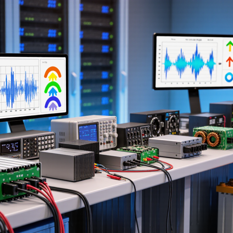
How to Choose the Right DC-DC Converter?
Define Input, Output, and Load Requirements: Voltage, Current, and Power
Begin with the real input range, not the nominal value printed on a system diagram. Record the lowest and highest source voltages, including startup dips, battery variation, and wiring losses. A converter rated for 12 volts may fail when the source briefly falls to 9 volts. Measure twice. Also check whether the input is steady, pulsed, or electrically noisy.
Define the output voltage and its permitted tolerance. A digital circuit may require a tight 3.3-volt rail, while a motor driver can accept wider variation. Calculate continuous current, peak current, and startup current separately. Then estimate power using output voltage multiplied by load current. Include conversion losses and leave practical thermal margin. Small details matter. A 10-watt load can create unexpected heat inside a sealed enclosure.
I once selected a converter from average current alone. The circuit reset whenever a wireless module transmitted, because its short current peak was much higher. That shortcut was wrong. Review the load profile with an oscilloscope when possible, and examine efficiency curves across the expected operating range. Check voltage ripple, transient response, isolation needs, protection features, and cooling conditions. Datasheet values are useful, but they depend on test setups. Your enclosure, airflow, cables, and temperature may differ. Recheck the design under worst-case conditions before approving the converter.
Compare typical converter requirements by defining the input voltage, regulated output voltage, load current, and output power.
Output power is calculated as Vout × Iout. Select a converter with an input-voltage range covering the full source variation and with sufficient current and power capacity for the load.
Topology should follow the power path, not habit. A buck converter suits a stable higher input and lower output. A boost converter raises voltage when the source falls short. Buck-boost designs handle battery voltage swings, but their control loop often needs more careful compensation. Isolated converters add a transformer, safety separation, and usually higher cost. They remain valuable when the input and output grounds must not connect.
Market demand makes this choice more important. The IEA’s Global EV Outlook 2024 reported almost 14 million electric car sales in 2023. IRENA’s Renewable Capacity Statistics 2024 recorded 473 GW of new renewable capacity in 2023. These systems face changing battery voltage, fast load steps, and strict thermal limits. In practice, I check input range, output current, ripple, efficiency, isolation voltage, and cooling space together. Choosing by nominal voltage alone is a common mistake.
Tips: Measure the worst case first. Test startup and short load transients. Compare losses at light and full load. A buck may look ideal, yet a wide battery range can require buck-boost operation. Isolation may solve a safety problem, but it can also increase size and leakage capacitance. I still revisit the topology after thermal testing; simulations can hide layout parasitics and unexpected EMI.
Choosing the right DC-DC converter requires more than checking its maximum efficiency. A converter rated above 90% may reach that figure only at a specific input voltage, load, and temperature. Real equipment rarely operates under one perfect condition. Measure efficiency across the expected load range, especially during startup, communication, and sleep cycles. A small difference can become significant in battery-powered products.
Standby power deserves equal attention. A converter drawing several milliamps while the system sleeps can quietly drain a battery overnight. Check quiescent current, shutdown current, and leakage through the enable circuit. Some devices disconnect the load during shutdown, while others leave a small current path. Test the complete circuit, not only the converter on a development board. Tiny indicators and monitoring chips can also consume more power than expected.
Thermal behavior can expose weaknesses. Run the converter inside its enclosure for at least several hours, then record the case temperature and output stability. Higher efficiency usually means less heat, but layout and airflow still matter. Choose adequate voltage margin and verify transient response with the actual load. Datasheet graphs are useful, but they are not your product. I have found that a converter with slightly lower peak efficiency can perform better overall when its standby loss remains low. That trade-off is easy to miss.
How to Choose the Right DC-DC Converter?
Ripple should be checked at the converter pins, not only at the distant load. Measure under load. Use a short ground spring and a defined bandwidth, because probe leads can create imaginary spikes. A practical target is often below 1% of output voltage, but sensitive converters may need tighter control. The measurement must include startup, load steps, and minimum input voltage. CISPR 32:2015 evaluates conducted emissions from 150 kHz to 30 MHz, so filtering decisions should reflect that range. A low-ripple waveform can still fail electromagnetic compatibility testing.
EMI testing should separate differential-mode noise from common-mode noise. Ferrite beads may reduce one problem while worsening another. The mistake is treating them as universal fixes. Thermal limits deserve the same discipline. JESD51 thermal measurement guidance shows why board copper, vias, airflow, and enclosure design strongly affect junction temperature. Calculate temperature rise at maximum load, then verify it in the final enclosure. Cold starts matter. IEC 60068-2-1 and IEC 60068-2-2 provide recognized cold and dry-heat test methods, but the converter’s actual operating range must match the system requirement. Check startup at the lowest temperature, not merely steady-state operation.
Leave margin for aging, blocked airflow, and component tolerance. A converter rated to 85°C may not survive a 75°C enclosure with poor ventilation. Review the datasheet curves, then test the worst realistic combination. That final step is often skipped, and it should not be.
| Converter Type | Typical Input / Output Range | Typical Power Range | Typical Switching Frequency | Output Ripple at Rated Load | Typical Efficiency | Primary EMI Considerations | Thermal Limits to Verify | Typical Operating Temperature Range | Recommended Verification Method |
|---|---|---|---|---|---|---|---|---|---|
| Buck Converter | Input: 6–60 V DC Output: 3.3–48 V DC, lower than input |
5 W–500 W | 100 kHz–2 MHz | 10–100 mV peak-to-peak, depending on load, layout, inductor, and capacitors | 85–96% | High-side switching-node radiation, input-current spikes, ringing, and common-mode noise. Keep the hot loop short and use appropriate input filtering. | MOSFET and diode or synchronous-rectifier losses, inductor temperature rise, capacitor ripple-current rating, PCB copper area, and enclosure temperature. | -40°C to +85°C ambient is common; higher-temperature versions may support up to +105°C or +125°C | Measure ripple with a short ground spring or coaxial probe. Check efficiency and component temperatures at minimum input, maximum input, minimum load, and full load. |
| Boost Converter | Input: 3–48 V DC Output: 5–100 V DC, higher than input |
5 W–300 W | 100 kHz–1.5 MHz | 20–200 mV peak-to-peak, with higher ripple possible at low input voltage and high output current | 80–94% | Pulsed input current, switching-node ringing, diode reverse-recovery noise, and elevated output-voltage stress. Input and output filters may both be required. | Inductor saturation current, switch voltage rating, diode or synchronous-rectifier losses, output capacitor ripple current, and thermal dissipation at minimum input voltage. | -40°C to +85°C ambient is common; derating may be required above +60°C | Test at the lowest input voltage and highest output power because input current and conduction losses are usually greatest there. |
| Buck-Boost Converter | Input: 6–36 V DC Output: 5–36 V DC, above or below input |
10 W–300 W | 200 kHz–1 MHz | 20–150 mV peak-to-peak under typical filtered conditions | 78–93% | More switching transitions than a basic buck or boost design, increased differential-mode noise, and possible output-voltage polarity or control-loop stress during input transitions. | Switch and inductor losses in both operating modes, current-limit behavior, thermal performance near the input-output crossover point, and transient stress. | -40°C to +85°C ambient is common; confirm derating curves for continuous full-power operation | Sweep the input voltage through the output-voltage region and verify ripple, efficiency, regulation, and temperature at both buck and boost operating points. |
| Isolated Flyback Converter | Input: 9–400 V DC Output: 5–48 V DC, isolated |
1 W–100 W | 50 kHz–500 kHz | 30–250 mV peak-to-peak before post-filtering | 70–90% | Transformer leakage-inductance ringing, drain-voltage overshoot, common-mode current across isolation capacitance, and switching-frequency harmonics. | Transformer core and copper losses, primary-switch avalanche or clamp losses, secondary-rectifier losses, isolation spacing, and safety capacitor temperature rating. | -40°C to +85°C ambient is common; high-voltage designs may require additional thermal derating | Verify isolation voltage, creepage, clearance, common-mode emissions, transformer temperature, drain overshoot, and output ripple at no-load and full-load conditions. |
| Resonant LLC Converter | Input: 200–450 V DC Output: 12–54 V DC, isolated |
100 W–3 kW | 70 kHz–500 kHz | 10–100 mV peak-to-peak after output filtering | 90–98% | Soft switching reduces turn-on losses and high-frequency noise, but transformer parasitics, gate-drive loops, rectifier commutation, and common-mode currents still require careful control. | Resonant-tank operating range, transformer temperature, synchronous-rectifier timing, magnetizing current, heatsink capability, and power loss during light-load operation. | -20°C to +85°C ambient is common; continuous full-load operation may require forced airflow | Verify zero-voltage switching over the complete input, load, and temperature range. Measure switching-node waveforms, transformer temperature, efficiency, and output ripple. |
| Non-Isolated POL Converter | Input: 4.5–24 V DC Output: 0.8–12 V DC |
3 W–200 W | 300 kHz–3 MHz | 5–50 mV peak-to-peak with suitable low-ESR capacitors | 85–95% | Fast switching edges can create localized electric and magnetic fields. Minimize the input hot loop, control ground return paths, and consider spread-spectrum operation. | High-current inductor losses, switching-device junction temperature, output-capacitor ripple current, thermal vias, and airflow around the PCB. | -40°C to +85°C ambient is common; many compact modules require derating above +70°C | Use an oscilloscope with proper probing, test load transients, inspect thermal images, and verify load regulation at the highest expected ambient temperature. |
| Automotive-Input DC-DC Converter | Input: 6–36 V DC typical operating range Transient withstand capability may need to exceed 40 V |
10 W–1 kW | 200 kHz–2 MHz | 20–150 mV peak-to-peak, depending on output current and input filtering | 85–96% | Cable-borne conducted emissions, load-dump energy, reverse-battery events, fast transients, and radiated emissions from long harnesses. | Cold-start current, maximum ambient temperature, enclosure heat transfer, input-protection losses, switching-device voltage margin, and connector temperature. | -40°C to +105°C is common; under-hood applications may require operation near +125°C | Test cold crank, load dump, reverse polarity, electrical fast transients, conducted emissions, radiated emissions, and full-load thermal performance. |
Safety should guide every DC-DC converter decision. Check whether the device meets relevant IEC, UL, or regional safety requirements. Requirements vary by application and market. Do not rely on a logo alone. Review the actual certification scope and test conditions. For isolated converters, inspect isolation voltage, creepage, and clearance distances. These details matter near high-voltage inputs. A compact enclosure can create hidden risks. Thermal behavior deserves equal attention. Measure surface temperature under maximum load, not only during a short bench test.
Tips: Look for overcurrent, short-circuit, overvoltage, overtemperature, and reverse-polarity protection. Confirm whether protection latches, retries, or shuts down permanently. Test recovery after a fault. A converter that survives one event may fail after repeated stress. Add input filtering when switching noise affects sensors or communication lines. Check the datasheet carefully. Marketing language can sound stronger than the test data.
Long-term reliability depends on derating, ventilation, component quality, and stable operating conditions. Avoid running continuously at the rated limit. Leave thermal and electrical margin. Review output ripple, startup behavior, load transients, and vibration requirements. In field evaluations, connectors and solder joints often deserve more attention than expected. No prediction is perfect. Ambient temperature, dust, and installation errors can change results. A small prototype test may still miss years of aging. Record measurements, repeat fault tests, and ask whether the converter remains safe after realistic abuse.
Not necessarily. Its peak efficiency may occur at one voltage, load, and temperature. Measure performance across startup, communication, and sleep cycles. A lower peak can still win.
Several milliamps can drain a battery overnight. Check quiescent current, shutdown current, and enable-circuit leakage. Small indicators may consume surprising power.
Test the complete circuit, not only the converter board. Include monitoring chips, indicators, sensors, and disconnected loads. Sleep mode can reveal hidden current paths.
Run the converter inside its enclosure for several hours. Record case temperature and output stability. Test maximum load, not just a short bench run. Airflow matters.
Look for overcurrent, short-circuit, overvoltage, overtemperature, and reverse-polarity protection. Confirm whether faults retry, latch, or shut down permanently. Recovery behavior matters.
Review applicable safety requirements and the actual test conditions. For isolated designs, inspect isolation voltage, creepage, and clearance. A compact enclosure may hide risks.
Thermal and electrical margin improve long-term reliability. Check ripple, startup behavior, load transients, ventilation, and vibration. Rated capacity is not a comfortable operating target.
Dust, heat, vibration, connectors, and solder joints can change results. Repeat fault tests under realistic conditions. No prediction is perfect. Small prototypes can miss years of aging.
Choosing the right DC-DC Converter begins with clearly defining the system’s input voltage range, required output voltage, load current, and total power demand. These factors determine whether a buck, boost, buck-boost, or isolated topology is most suitable. A buck converter is ideal for stepping voltage down, while boost and buck-boost designs support higher or varying output requirements. Isolation may be necessary when enhanced protection or separate electrical domains are required.
Beyond basic conversion, evaluate efficiency targets above 90%, standby power consumption, output ripple, electromagnetic interference, and thermal performance. The converter should operate reliably across the expected temperature range and include appropriate safety certifications and protection features, such as overvoltage, overcurrent, short-circuit, and thermal shutdown protection. Finally, consider component quality, design stability, service conditions, and expected operating life to ensure dependable long-term performance. A balanced assessment of electrical, thermal, safety, and reliability requirements will help identify the most appropriate solution for the application.
